
Function
Enter spring stiffness per unit supporting area of planar or solid elements to create elastic spring supports. Elastic Link elements may be created simultaneously. This function is mainly used to define a number of elastic supports on surfaces represented by the modulus of spring. For example, if the user wishes to define elastic supports for subgrades of foundations or underground structures, subgrade springs will be automatically entered at each node represented by concentrated stiffness. This function enables the user to specify the surface or line stiffness without having to worry about the discretization (sizes) of elements, which is automatically taken care of by the program.
Call
From the Main Menu select [Boundary] tab > [Springs] group > [Surface Spring]
Input
Click the [...] button to the right of Surface Spring Supports : Display the Point Spring Support Table
Note
The data entered in Surface Spring Supports are converted into Point Spring Supports or Elastic Link data and saved as such.
Boundary Group Name
Select a Boundary Group in which the specified boundary condition is included. Select "Default" if Group assignment is unnecessary. Click the [...] button to the right to prompt the "Define Boundary Group" dialog box to add, modify or delete Boundary Groups.
Surface Spring
Convert to Nodal Spring
Select a type of data to be created using the stiffness per unit area.
Point Spring : Point spring support
Elastic Link : Elastic link element
Distributed Spring
Enter the distributed spring stiffness to beam, planer or solid elements in order to consider elastic support conditions of subgrades.
Element Type
Assign the type of elements for which elastic spring supports or elastic link elements are to be created.
Frame : Create elastic spring supports or elastic link elements on the nodes of beam elements.
Width : Width of beam elements to calculate the support stiffness per unit length.
Planar : Create elastic spring supports or elastic link elements on the nodes of planar elements.
Solid (Face) : Create elastic spring supports or elastic link elements on a face of solid elements.
Solid (Node) : Create elastic spring supports or elastic link elements on the nodes of solid elements
Note
If the element type is selected as solid, a face of the elements must be specified.
Spring Type
Linear
Modulus of Subgrade Reaction : Subgrade stiffness
Kx : Stiffness per unit area in the node's local x- direction (GCS X-direction)
Ky : Stiffness per unit area in the node's local y- direction (GCS Y-direction)
Kz : Stiffness per unit area in the node's local z- direction (GCS Z-direction)
Comp.-only / Tens.-only
Direction : Direction of the Point Spring
Normal(+) : Normal (+ dir) to the surface (average normal direction of surfaces connected to the node defined with Point Spring)
Normal(-) : Normal (- dir) to the surface (average normal direction of surfaces connected to the node defined with Point Spring)
Note
The normal direction of planar elements is defined by the right hand rule based on the node entry sequence. For solid elements, the normal direction (+) is oriented away from the surfaces of the elements.
UCS-x(+) : UCS +x-direction (GCS +X-direction)
UCS-x(-) : UCS -x-direction (GCS -X-direction)
UCS-y(+) : UCS +y-direction (GCS +Y-direction)
UCS-y(-) : UCS -y-direction (GCS -Y-direction)
UCS-z(+) : UCS +z-direction (GCS +Z-direction)
UCS-z(-) : UCS -z-direction (GCS -Z-direction)
Modulus of Subgrade Reaction : Subgrade stiffness
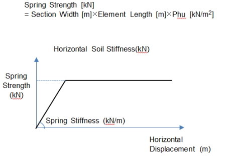
Bilinear
Bilinear spring type to simulate the strength limit of the soil. The strength limit should be defined by the user.
Modulus of Subgrade Reaction: Subgrade stiffness
Kx : Stiffness per unit area in the node's local x- direction (GCS X-direction)
Ky : Stiffness per unit area in the node's local y- direction (GCS Y-direction)
Kz : Stiffness per unit area in the node's local z- direction (GCS Z-direction)
Phu : Strength limit of the soil (force/length2)
When Elastic Link is selected
Element Type
Assign the type of elements for which elastic spring supports or elastic link elements are to be created.
Frame : Create elastic spring supports or elastic link elements on the nodes of beam elements.
Width : Width of beam elements to calculate the support stiffness per unit length.
Planar : Create elastic spring supports or elastic link elements on the nodes of planar elements.
Solid (Face) : Create elastic spring supports or elastic link elements on a face of solid elements.
Solid (Node) : Create elastic spring supports or elastic link elements on the nodes of solid elements
Note
If the element type is selected as solid, a face of the elements must be specified.
Direction : Direction of the elastic link
Normal(+) : Normal direction of the surface (average normal direction of surfaces connected to the node defined with Elastic Link)
Normal(-) : Normal direction of the surface (average normal direction of surfaces connected to the node defined with Elastic Link)
Note
The normal direction of planar elements is defined by the right hand rule based on the node entry sequence. For solid elements, the normal direction (+) is oriented away from the surfaces of the elements.
UCS-x(+) : UCS +x-direction (GCS +X-direction)
UCS-x(-) : UCS -x-direction (GCS -X-direction)
UCS-y(+) : UCS +y-direction (GCS +Y-direction)
UCS-y(-) : UCS -y-direction (GCS -Y-direction)
UCS-z(+) : UCS +z-direction (GCS +Z-direction)
UCS-z(-) : UCS -z-direction (GCS -Z-direction)
Modulus of Subgrade Reaction : Subgrade stiffness
Length of Elastic Link : Length of elastic link element. The length dose not affect the analysis. It is simply required to define a vector internally in the solver.
Tens. Only, Comp.-Only : Check in an option to assign elastic link with tension-only or compression-only elements
When Distributed Spring is selected
Element Type
Assign the type of elements for which elastic spring supports or elastic link elements are to be created.
Frame : Create distribute spring supports along the length of the beam element.
Selection
Local Axis : Direction of the distributed spring
Width : Width of beam elements to calculate the support stiffness per unit length.
Planar(Face) : Create distributed spring supports on the face of planer elements.
Planar(Edge) : Create distributed spring supports on the edge of Planer elements.
Solid (Face): Create distributed spring supports on the face of solid elements.
Note
If the element type is selected as solid or Planar(Edge) and the selection is selected as Element, a face of the elements must be specified.
Spring Properties
Type
Linear Type : Enter the stiffness of linear elastic spring.
Compression-only/Tension-only Type : Enter the compression-only/ tension-only type elastic spring.
Modulus of Subgrade Reaction : Subgrade stiffness
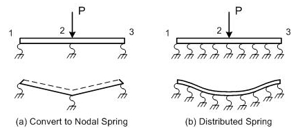
Note Difference between Convert to Nodal Spring and Distributed Spring
When Convert to Nodal Spring is selected, springs are entered at the nodes of the elements. When Distributed Spring is selected, springs are uniformly distributed on a face or edge of the elements.
|
Convert to Nodal Spring |
Distributed Spring (Winkler Spring) |
|
|---|---|---|
|
Spring location |
Nodes of elements |
Distributed on the elements |
|
Unit of reaction |
kN |
Beam: kN(kN/M) Planar or Solid: kN(kN/M2) |
|
Deformation |
Concentrated at the nodes |
As element stiffness increases, deformations are distributed throughout the elements. |