Function
Constrain certain degrees-of-freedom of Slave Nodes to a Master Node.
If a degree-of-freedom of a particular slave node is constrained to a master node by this command, "Rigid Link" relationship is established for the relevant degree-of-freedom. All the attributes (nodal load or nodal mass) including the stiffness component of the slave node are converted into an equivalent component of the master node.
Call
From the Main Menu select [Boundary] tab> [Link] group > [Rigid Link]
Input
Click the [...] button to the right of Rigid Link : Display the Rigid Link Table
Boundary Group Name
Select a Boundary Group in which the specified boundary condition is included. Select "Default" if Group assignment is unnecessary. Click the [...] button to the right to prompt the "Define Boundary Group" dialog box to add, modify or delete Boundary Groups.
Option
Add/Replace : Assign selected nodes as slave nodes or modify rigid link conditions
Delete : Delete rigid link conditions of selected nodes
Master Node Number
Enter a master node number. Type in directly the master node number on the keyboard, or click the entry field and the relevant node.
Note that the slave nodes are assigned by Select.
Note
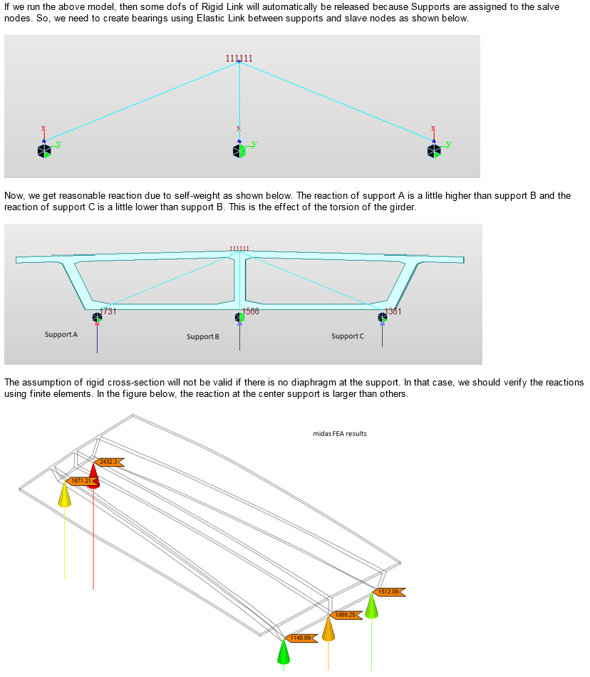
Reactions of slave nodes were printed at the slave nodes. From V690, slave node reactions are combined and printed as the vertical load and moments at the master node.
Release Slave Nodes Without Specifying Master Nodes : Release slave nodes without selecting the master node. This function can be used in the Delete option only.
DOF of Rigid Link
Assign the degree-of-freedom about GCS degree-of-freedom to be slaved to the master node.
DX : Displacement degree-of-freedom in GCS X-direction
DY : Displacement degree-of-freedom in GCS Y-direction
DZ : Displacement degree-of-freedom in GCS Z-direction
RX : Rotational degree-of-freedom about GCS X-axis
RY : Rotational degree-of-freedom about GCS Y-axis
RZ : Rotational degree-of-freedom about GCS Z-axis
Copy Rigid Link
Copy the rigid link conditions defined in DOF of the Rigid Link and simultaneously assign the identical conditions to selected nodes.
Axis : Assign the axis direction to be copied
Distances : Assign the copy distances
Note
Nodes must exist at the location to which the Rigid Link will be copied for master and slave nodes.
Typical Types
The following buttons simplify the individual data entries described above.
The Rigid Body button : Rigid Body Connection
The Plane X-Y button : Rigid Plane Connection in GCS X-Y plane
The Plane Y-Z button : Rigid Plane Connection in GCS Y-Z plane
The Plane X-Z button : Rigid Plane Connection in GCS X-Z plane
Q & A
Revision of Gen NX
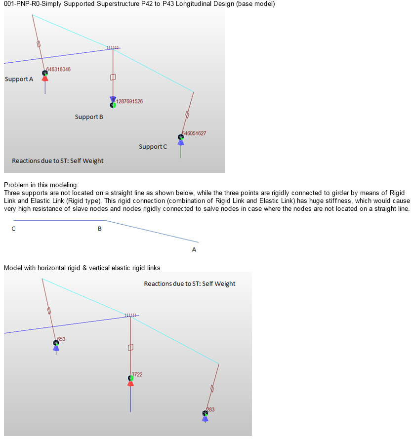
The models attached herewith are very puzzling and raise some doubts about the link connectivity. One of the models is a base model. The models with horizontal link and inclined link were later made for our verification. The support nodes (at 3 support location) were shifted in our test models and placed equidistant from the central support node. That brought down the abnormal reaction values. However, with everything else being the same, if the horizontal and vertical link assembly is changed to inclined link assembly, the vertical reactions change! Why is that? Supporting nodes and support conditions remain same. Just the change in flow of force due to links is changing vertical reactions drastically. This shouldn't be happening. A simple test model made showed that. Why is that not the case with the attached files? Please verify and let me know.
A1.