
機能
鉄筋コンクリート部材の設計による検定比を数値と等高線で表示します。
配筋情報による設計結果を確認する場合には鉄筋の直径と配筋間隔、そして所要鉄筋断面積で確認することができます。
あばら筋、帯筋の本数を各方向ごとに出力します。
呼出
リボンメニュー:設計 > RC設計 > 結果 > RC部材設計結果 > RC設計
入力
荷重ケース/荷重組み合わせ
希望する荷重ケース、荷重組合わせ条件または荷重エンベロップ条件を選択します。
荷重組合わせ条件を新規に入力したり、修正または追加する場合には右側のをクリックします。(静的荷重ケース/荷重組合わせを参照)
検定比成分
設計結果出力時、特定の値以上の応力比のみを画面に出力します。
軸力 : 軸方向の強度比成分
せん断-y : 強軸方向のせん断力に対する検定比
せん断-z : 弱軸方向のせん断力に対する検定比
曲げ-y : 強軸回りの曲げモーメントに対する検定比
曲げ-z : 弱軸回りの曲げモーメントに対する検定比
組合わせ : 最大組合わせ応力度比の成分
組合わせオプションを選択すれば、配筋情報による設計結果を確認することができます。
梁の場合のCombined = max [曲げ比(M_Ed/M_Rd), せん断比(V_Ed/V_Rd)]
柱の場合のCombined = max [軸力比(N_Ed/N_Rd), モーメント比(M_Rd/M_Rd)]
ここで :
(M_Ed/M_Rd) = √(M_Edy2+M_Edz2) / √(M_Rdy2+M_Rdz2).
表示形式
鉄筋
配鉄情報を出力します。
鉄筋 : 鉄筋の直径及び配筋間隔を出力
面積 : 必要鉄筋断面積を出力
表示 : 出力する要素の種類を選択
柱サイズ : 出力される柱断面の大きさを決定
数値オプション : 出力される結果値の有効桁数を決定
配鉄情報の表示方法
'RC / SRC設計結果'機能で配鉄情報を鉄筋の直径、配筋間隔、必要鉄筋断面積で表現できます。
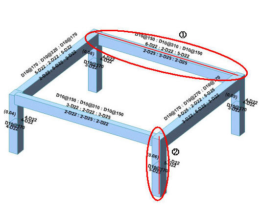
1) 鉄筋で '鉄筋'を選択した場合
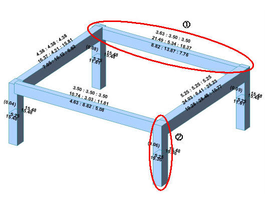
2) 鉄筋で '面積'を選択した場合
1. 梁部材の配筋情報の表示方法
上の図1), 2)で ①に位置した梁部材の設計結果を確認します。
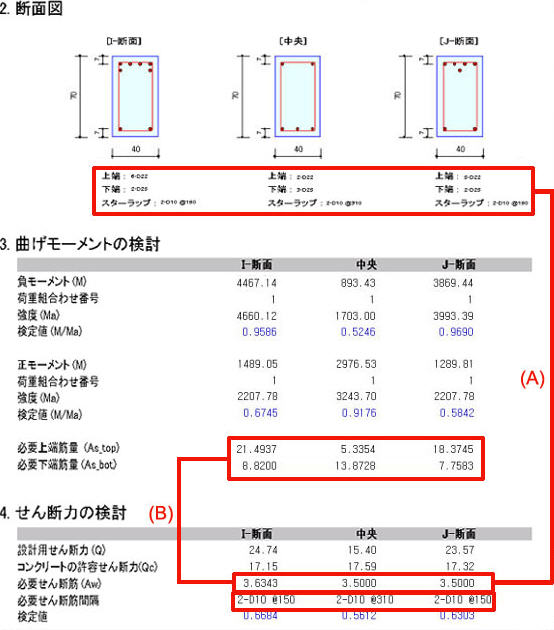
3) 梁部材設計結果
図1)で鉄筋オプションで'鉄筋'を選択すれば、図3)の(A)にある鉄筋直径及び配筋間隔が出力されます。
図1)で鉄筋オプションで'面積'を選択すれば、図3)の(B)にある必要鉄筋断面積が出力されます。
2. 柱部材の配筋情報の表示方法
上図1), 2)で ②に位置した柱部材の設計結果を確認します。
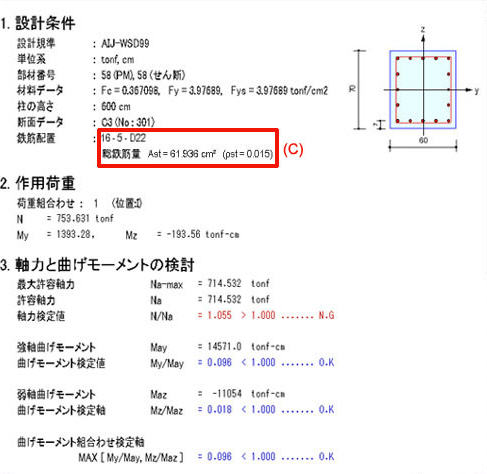
4) 柱部材の設計結果
主筋とせん断筋を区分して出力
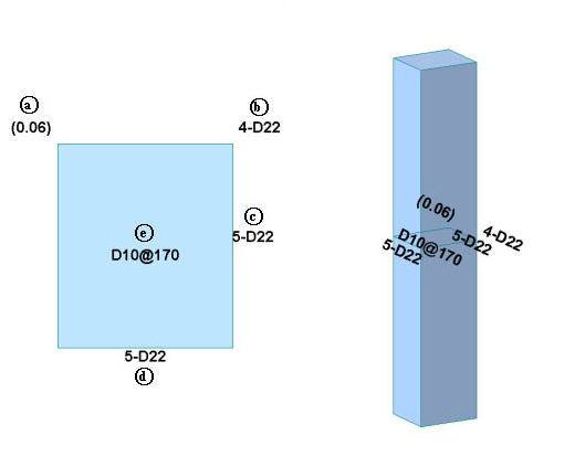
5) '鉄筋'を選択して柱の鉄筋情報を出力
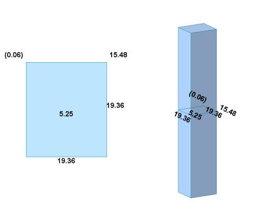
6) '面積'を選択して柱の鉄筋情報を出力
図5)で出力された鉄筋情報は次の通りです。
a(Uc) :柱の軸力比(N/(Fck X Ag))
b(As-corner) :柱のコーナーに位置した鉄筋の数及び面積
例) 4-D22 = 4 X 3.871 = 15.48 cm2
c, d(Asy, Asz) :柱断面の一辺の1軸配筋された鉄筋の数及び面積
e(Asv) :柱の帯筋間隔, Sc範囲内の帯筋面積
上のb, c, dに表現された鉄筋情報を利用して全体の鉄筋個数を計算すれば、
b+ ((c - 2) + (d - 2)) X 2 = 4 + ((5 - 2) + (5 - 2)) X 2 = 16
鉄筋の横配列数(Asz)=5
16-5-D22 (図4)の(C)と一致)
3. 壁の配筋情報の表示方法
図7), 8)で①に位置した壁の設計結果を確認する。
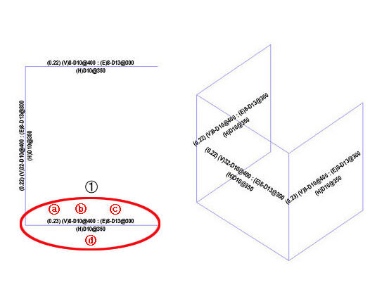
7) '鉄筋'を選択して壁鉄筋情報を出力
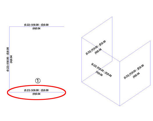
8) '面積'を選択して壁鉄筋情報を出力
図7). 8)で出力された壁鉄筋情報は次の通りです。
a(Uc) :壁の軸力比(N/(Fck X Ag))
b(V)12-D13@300 :垂直鉄筋数と間隔、または単位長さ当たりの垂直鉄筋量(cm2/cm)
c(E)8-D13@300 :端部の鉄筋数と間隔、または全体の垂直鉄筋量(cm2)
d(H)D10@170 :垂直鉄筋数と間隔、または単位長さ当たりの垂直鉄筋量(cm2/cm)
数値を表示する断面(梁)
梁部材のどの位置の検定結果を表示させるかを選択します。 "表示形式"で"数値"を選択した場合にのみ使うことができます。
I, 中央, J : 検定比が表示される位置を指定します。ただし、ユーザーが直接指定することはできず、 下の"最大値"、または"すべて"に応じてチェックマークが自動で付けられます。
最大値 : 梁部材の検定比の最大値を表示します。
すべて : 梁部材の各位置に対する検定比を表示します。
 : 入力した値を選択した部材に適用します。
 : ダイアログを閉じます。
For Shear Reinforcement :
Ratio of provided shear reinforcing steel per unit spacing to sectional width.
Display : Select the types of elements for which design reinforcing information will be displayed.
Output Component : Select the component to be displayed.
Ratio of Axial Stress
Main Rebar : Main rebar design result
Shear Reinforcement : Shear reinforcement design result
Column Section Size : Display of column section sizes can be scaled.
Value Option : Specify the number of decimal points for displayed values.
Note. Display of reinforcement
From the V600 of MIDAS/Gen, reinforcing information such as rebar diameter, rebar spacing and required reinforcing steel area can be checked in 'Concrete / SRC Design Result'.
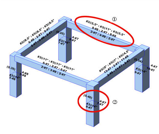
Fig. 1) When 'Rebar' is selected in Reinforcement
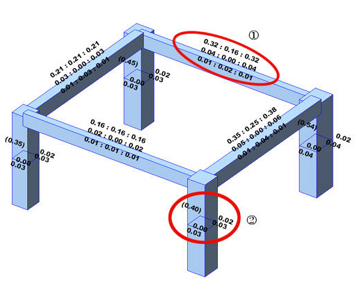
Fig. 2) When 'Area' is selected in Reinforcement
1. Rebar information for beams
Design results for the beam ① in the Figs. 1) & 2) above are produced.
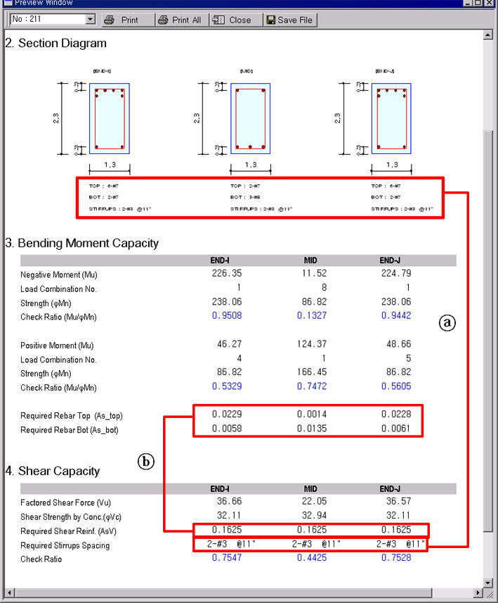
Fig. 3) Beam design results (Graphic)
The rebar diameter and spacing denoted by A in Fig. 3) are produced when 'Rebar' is selected in the Reinforcement option in Fig. 1). If 'Area' is selected, the required reinforcing steel areas are produced as denoted by B in Fig. 3).
2. Rebar information for columns
Design results for the column ② in the Figs. 1) & 2) above are produced.
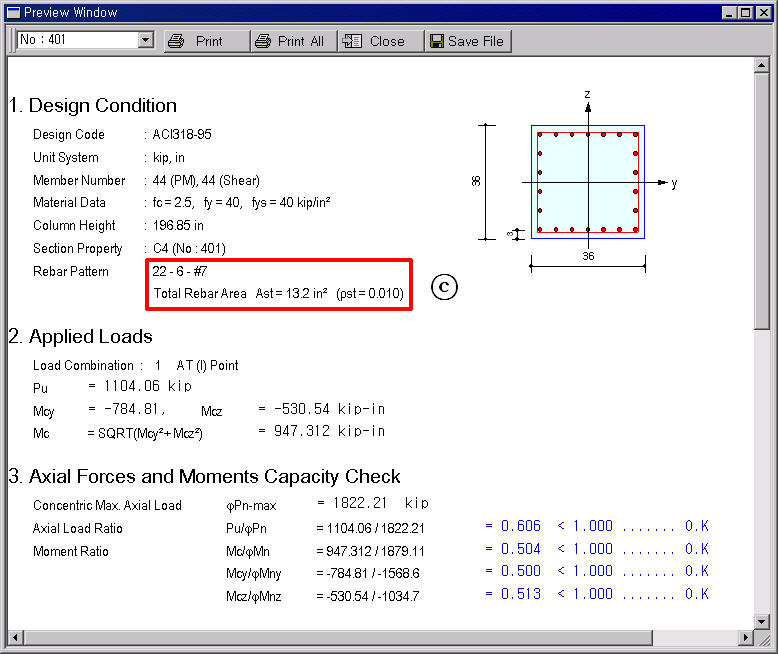
Fig. 4) Column design results (Graphic)
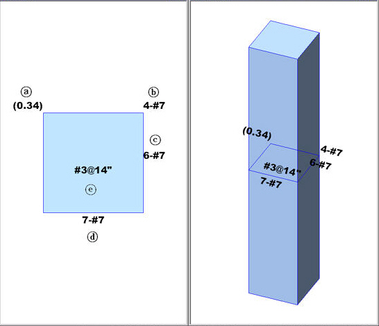
Fig. 5) Reinforcing information of column by selecting 'Rebar'
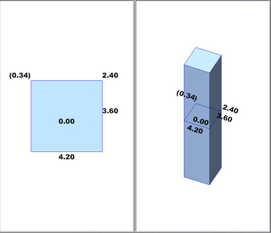
Fig. 6) Reinforcing information of column by selecting 'Area'
The following outlines the reinforcing information in Figs. 5) & 6) :
a. (Uc) : Ratio of axial stress of the column (N/(fc' X Ag))
b. (As-corner) : Number of corner rebars & rebar area
Ex.) 4-#7 = 4 X 0.6 = 2.4 in2
c & d (Asy, Asz) : Number of rebars and rebar area on a single side
e. (Asv) : Tie (shear) reinforcing spacing of column, Sc and rebar area within the spacing
Based on the reinforcing information noted at b, c & d above, the total number of rebars then becomes,
b+ ((c - 2) + (d - 2)) X 2 = 4 + ((6 - 2) + (7 - 2)) X 2 = 22
The number of rebars on one side (Asz)=5
22-6-#7 (See C in Fig. 4)
3. Rebar information for walls
Design results for the wall ① in the Figs. 7) & 8) are produced.
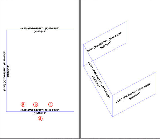
Fig. 7) Reinforcing information of wall by selecting 'Rebar'
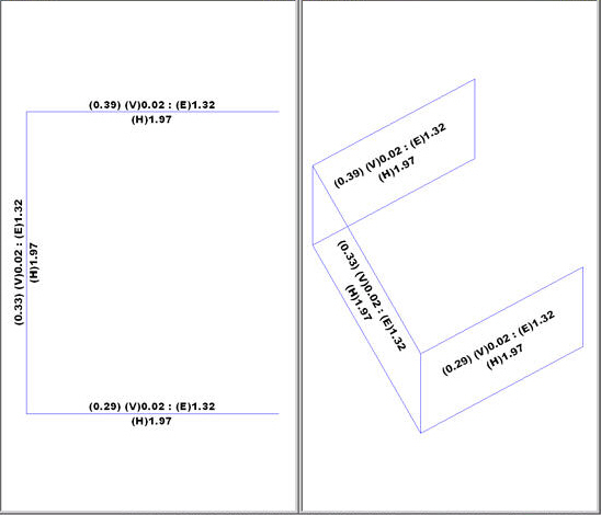
Fig. 8) Reinforcing information of column by selecting 'Area'
The following outlines the reinforcing information in Figs. 7) & 8) :
a. (Uc) : Ratio of axial stress of the wall (N/(fc' X Ag))
b. (V)8-#4@16" : Number of vertical rebars and spacing or vertical reinforcing steel area per unit length (in2/in)
c. (E)12-#3@6" : Number of end rebars and spacing or total amount of reinforcing steel (in2)
d. (H)#3@11" : Number of horizontal rebars and spacing or horizontal reinforcing steel area per unit length (in2/in)
Output Section Location(Beam)
Check RC member design results by sectional locations. It can be used only when "Values" of "Type of Display" is selected.
I, Center, J : Represent the RC beam member's sectional locations. The user can not select the locations. It is automatically selected following the selection of "Max" or "All".
Max : Maximum values appear at every RC beam member.
All : Values appear at each location of RC beam members.
The Applu button : Apply the entered values to the selected members.
The Close button : Close the Entry Dialog Bar.