Function
Automatically generate a mesh by specifying an area.
Call
From the Main Menu select [Node/Element] tab > [Mesh] group > [Mesh] > [Auto-mesh]
Input
Mesher
Method : Specify an area for the mesh. There are three ways of specifying an area: Nodes, Line Elements, Planar Elements
Nodes : Selected nodes are displayed according to the order of selection. The selected nodes should exist on the same plane to create a mesh.
Line Elements : Selected line elements are displayed in sequential order. The selected line elements should exist on the same plane to create a mesh.
Planar Elements : Selected planar elements are displayed in sequential order. The planar elements need not be on the same plane to create a mesh.
Type
Quadrilateral : Generate a mesh using quadrilateral elements.
Quad+Triangle : Generate a mesh using quadrilateral elements and triangular elements.
Triangle : Generate a mesh using triangular elements.
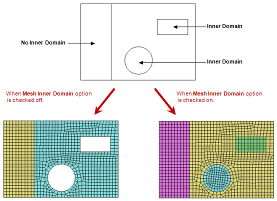
Mesh Inner Domain
If this option is selected and there is an inner domain within the mesh area, a mesh is generated in the domain too.
Include Interior Nodes
If this option is selected and there is a node within the area to be meshed, a mesh is generated considering the node. The interior nodes can be automatically detected or specified by the user.
Include Interior Lines
If this option is selected and there is a line within the area to be meshed, a mesh is generated considering the line. The interior lines can be automatically detected or specified by the user and can be from line elements, planar elements or solid elements.
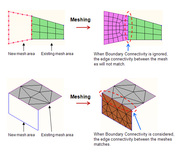
Include Boundary Connectivity
Consider the mesh connectivity of adjacent meshes.
Mesh Size
Define the size of the mesh elements. The size can be defined by a length or by the number of divisions.
Length : Define the side length of the mesh elements.
Division : Define the number of divisions for the reference elements comprising the area to be meshed.
Property
Element Type
Select the element type of the planar mesh elements to be created. There are four element types available: Plate, Plane Stress, Plane Strain and Axisymmetric. The [...] button to the right becomes active when the element type is Plate or Plane Stress. Click the button to define the Element Sub Type.
Material : Enter the material property of the planar mesh elements to be created. Click the [...] button to the right to invoke the Material dialog box.
Thickness : Enter the thickness data of the planar mesh elements to be created. Click the [...] button to the right to invoke the Thickness dialog box.
Domain
Name : Define the name of Domain.
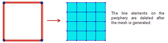
Delete Boundary Line Elem.
If this option is selected, the line elements on the periphery of the mesh area are deleted after the mesh is generated.
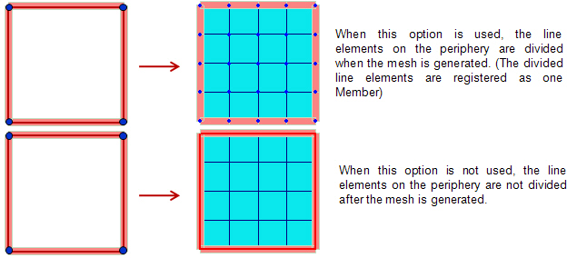
Subdivide Boundary Line Elem.
This option can be used when 'Delete Boundary Line Elem.' is not selected. If this option is selected, the line elements on the periphery of the mesh area are divided according to the mesh size. The divided line elements are registered as a Member and it can be checked in the Member Assignment dialog.