
Function
- The wizard automatically generates grillage model with the longitudinal members coincident with longitudinal webs for multicellular bridge decks..
- With MIDAS/Civil, effective behavioral analysis of various phenomena such as reaction distribution, torsional behavior, and interaction can be performed by supplementing the limitations of the Single Beam model.
- Define the road alignment information, the span information, and the boundary conditions etc in the Layout tab.
Call
From the main menu, select [Structure] tab > [PSC Bridge] group > [PSC Box Bridge] > [Grillage Model]
Input
Grillage Model_Layout dialog box
Model Type
2D
Divide the longitudinal section of the Single Beam model into vertical segments and create a 2D grid model.
3D
Create a spatial grid model by dividing the longitudinal section of the Single Beam model vertically and horizontally.
Bent Cap/Abut./Diapharagm Member Type
When Frame selected : Create Bent Cap/Abut./Diaphragm with Frame element.
When Plate selected : Create Bent Cap/Abut./Diaphragm with Plate element.
Abut. : Transverse member generated at the beginning of the first span and at the end of the last span
Bent Cap : Transverse member generated at the beginning/end of the span except for Abutment.
Diaphragm : Transverse member created at a distance of Location input value from the start point of the corresponding Span when Diaphragm option in the Span tab is checked.
Bridge Material
Select the Material property of the bridge. The material should be defined in advance. Click to define a new material.
Span Information
Specify the spans sequentially. Example - 300, 400, 2@300, 100
When the number of spans is changed, the number of spans in the Span Information tab should be modified.
Skew Angle
Skew angle of the bridge in plan (θ deg)
Input range is from (-)45° to (+)45°, (+) indicates counter-clockwise direction.
Click Advanced... to enter different skew angles by spans.
Offset
Distance between the reference line and the center line of the bridge.
Alignment of Transverse Members
Transverse members may be orthogonal or skewed with respect to the longitudinal members.
Perpendicular
Skewed
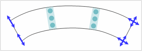
Radius
Specify the radius in the case of a horizontally curved bridge.
Convex
Convex curvature (center of circle located below)
Concave
Concave curvature (center of circle located above)
Multi-Curve
Click Advanced... to input multi-curves.
The curvature can be defined as the combination of a straight line and a curve.
Boundary
Integral Type
In case of the integral bridge, enter data for the substructure as follows.
Abutment Section : Enter abutment section
Abutment Height : Enter abutment height
Pier Section : Enter pier section
Pier Height : Enter pier height
Bottom of Abutment / Pier : Boundary conditions of substructure
Fixed : Set as a fixed support.
Spring Support : Set as a spring support. Specify the horizontal and vertical spring stiffness. Click Advanced... if spring stiffness is different for each support.
Bearing Type
When superstructure and substructure are connected with bearings:
Supports : Bearings are represented by fixed / free support. Once the position of fixed support is determined, all the other supports are considered as free support longitudinally.
Elastic Link : Bearings are represented by Elastic Link. Enter the stiffness of bearings by directions for the abutments and the piers. Click Advanced... to enter different stiffness for different supports.
Fixed Support : Select longitudinally fixed support. Longitudinally and transversely fixed bearing is used as a reference point for the determination of the direction of free bearings in the In Line with Fixed Support option.
Direction : Choose the method of determining direction of the free bearings.
Tangential : The restraint-free direction is tangent to the longitudinal axis of the bridge. (i.e. tangent to the curvature of a curved bridge or in the direction of a straight bridge)
In line with Fixed Support : The restraints are freed in the directions from the individual supports to the fixed support.
Tangential
in Line with Fixed Support
Hybrid Type
When the piers are integral with the deck structure but the abutments are not integral with the deck structure:
Abut : Bearing
Supports : Bearings are represented by fixed / free support. Support conditions are automatically considered as shown below. Longitudinal movement for the start abutment is fixed. All the other supports are considered as free support both longitudinally and transversely.
Support conditions
Elastic Link : Bearings are represented by Elastic Link. Enter the stiffness of bearings by directions for the abutments. Click Advanced... to enter different stiffness for different abutments.
Pier : Integral
Pier Section : Enter pier section
Pier Height : Enter pier height
Bottom of Pier : Boundary conditions of piers
Fixed : Set as a fixed support.
Spring Support : Set as a spring support. Specify the horizontal and vertical spring stiffness. Click Advanced... if spring stiffness is different for each pier.
Open...
Open the data saved as in the *.wzd file type in the Grillage Model Wizard. By using this function, we can re-execute midas Civil and subsequently check and modify the previously entered data within the Wizard.
Save As...
Save the data entered in the Grillage Model Wizard as the *.wzd file type.