
機能
-
PC合成桁橋ウィザードについて
プレキャスト桁 は、工場で製作された後、現場へ輸送・架設される部材であり、橋梁の迅速な施工を可能にし、経済的な手法として広く採用されています。
スプライス桁 は、比較的長い複数のセグメント(主桁部材)として製作され、現場で一体化される橋梁構造です。各セグメントは連続的にポストテンションを施すことで、接合部の剛性を高めます。
プレキャスト桁およびスプライス桁は、いずれもプレキャスト・プレストレスコンクリート部材であり、単純桁橋から多径間橋まで幅広く適用可能です。
プレ/ポストテンション合成桁橋ウィザード(以下、「PC合成桁橋ウィザード」) の主な目的は、3D有限要素モデルを短時間で効率的に作成できるようにすることです。
本ウィザードでは、直線橋・曲線橋・斜橋などのさまざまな橋梁形式に対応したプレキャスト桁およびスプライス桁のモデルを作成でき、下部構造のモデリングも可能です。また、格子法や全板要素法など、異なるモデリングアプローチを選択できます。さらに、荷重条件や施工ステップも、直感的なインターフェースを通じて簡単に設定できます。
ウィザードは高い柔軟性を備えており、初期データ入力後も自由に修正が可能です。入力データはファイルとして保存でき、後から開いて再利用することもできます。
- ウィザードの構成
ウィザードには、次の5つの主要なタブがあります。
レイアウト:橋の基本的な形状と支承の特性を定義します。
断面:材料と断面の特性、および桁やデッキの位置を定義します。
PC鋼材:シンプルな入力で、さまざまな種類のPC鋼材を定義します。
荷重:荷重条件を定義します。
施工段階:施工段階の条件を定義します。
- すべてのウィザードの入力は *.wzd ファイル形式に保存することができます。
- 開く...PC合成桁橋ウィザードで保存された *.wzd ファイルのデータを読み込むことで、以前に入力したデータを再実行、確認、修正することができます。
- 別名で保存...PC合成桁橋ウィザードに入力したデータを *.wzd ファイルとして保存する機能です。
- ウィザードを使用すると、PC合成桁橋モデルを生成できます。レイアウトタブで、橋の全体的なレイアウト、境界条件などを定義します。
経路
- メインメニュー:[ウィザード]タブ > [PC橋]グループ > [PC合成桁橋]
入力
図. PC合成桁橋ウィザードダイアログ・ボックス
桁タイプ
ウィザードの構成は、桁タイプによって異なります。
プレキャスト桁タイプ :主桁は工場で製作され、1径間ずつ現場で架設されます。
スプライス桁タイプ : 主桁は複数のセグメントに分割して製作され、接合部でセグメントが分断された状態になります。
モデルタイプ
デッキと桁のモデリングは、すべてを梁要素で表現する方法や、デッキを板要素、桁を梁要素とする方法など、さまざまなアプローチが可能です。
全て梁要素 : 桁を梁要素としてモデル化し、断面特性で定義された合成断面を適用
デッキ:板要素 桁:梁要素 : デッキは板要素、桁は梁要素としてモデル化
全てフレーム(非合成):
主桁の種類やモデリング手法(全て梁要素、デッキを板要素として定義 など)に応じて、入力メニューがカスタマイズされます。
なお、選択したモデリング手法に関わらず、横桁や下部構造のモデル化には梁要素のみが使用されます。
支間情報
支間長を順番に指定します。
例えば、「30、25、2@20、30」と入力すると、計5つのSpanで、1径間目から5径間目までの長さがそれぞれ30m、25m、20m、20m、30mとなります。
支間情報は基準線に基づいて設定します。橋梁モデルが斜角または曲線の場合でも、すべての支間情報は基準線上の寸法として入力します。また、横方向デッキ要素の間隔や、中間横桁(断面タブ)の配置寸法も基準線の位置を基準に設定されます。
デッキ幅
橋全体のデッキ幅を指定します。デッキ幅は、ダミーデッキ部材の作成や、「デッキ:板要素 / 桁:梁要素」モデリングタイプにおいて、断面特性からデッキ情報を除外する際に使用されます。
レイアウト・オフセット
基準線から橋梁の中心の距離
斜角
橋梁の各支点位置における平面上の斜角(θ度) を指定します。
ダイアフラムは指定した支点の斜角に沿って配置されます。横桁要素も、角度タイプが「斜角」の場合はこの斜角に従います。ただし、主桁タイプがプレキャスト かつ 桁の配置条件が「同じ間隔」 の場合、基準線上の支点のみがこの斜角に従います。ダイアフラムの配置には各支点位置の斜角ではなく、基準支点の斜角が適用されます。
斜角は-75度から75度の範囲で指定する必要があります。
連続梁
隣接する支間間のプレキャスト桁に対して非連続条件を適用し、両支間をつなぐ床版部分で曲げモーメントを解放します。
図. 連続梁オプション
半径
水平方向にカーブした橋梁の半径を指定します。
凸型:凸曲率(円の中心が曲線の下側に位置する場合)です。
凹型 : 凹曲率(円の中心が曲線の上側に位置する場合)です。
入力された斜角と曲率半径の情報に基づき、節点座標軸が自動的に定義されます。
図. 半径オプション
マルチカーブ
入力方法として「カーブデータ」または「座標データ」を選択し、「詳細...」をクリックして、複数のカーブを入力します。
カーブデータ : マルチカーブ詳細オプションを使用すると、直線および曲線形状の組み合わせに対して曲率を定義することもできます。
平面カーブ : 水平曲線を定義します。
直線 : 直線の始点と終点を定義します。
円曲線 : 円曲線の始点と終点、およびカーブ点の半径を指定します。
緩和曲線 :緩和曲線の始点と終点、およびカーブ点の半径を指定します。
垂直カーブ
ステーション : 垂直カーブの基準点を入力します。
高さ: 垂直カーブの高さを入力します。
カーブ長さ : 垂直カーブの水平長さを入力します。
横断勾配
ステーション : 横断勾配の基準点を入力します。
片勾配 : 横断勾配の傾斜を入力します。
例
|
|
ステーション(m) |
高さ(m) |
カーブ長さ(m) |
|
1 |
0 |
0 |
0 |
|
2 |
50 |
20 |
40 |
|
3 |
100 |
0 |
0 |
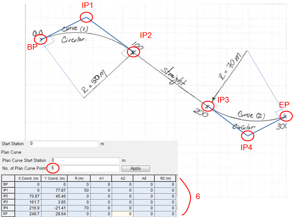
座標データ : マルチカーブ詳細オプションを使用すると、直線および曲線形状の組み合わせに対して曲率を定義することもできます。
開始ステーション : 橋梁モデリングの開始位置。
平面カーブ : 水平曲線を定義します。
平面カーブの開始位置 : 平面カーブの開始位置を定義します
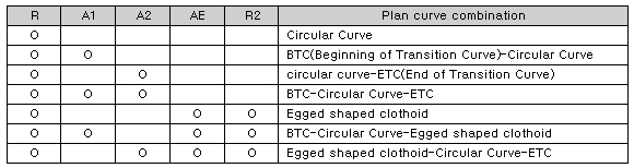
単位 : 平面カーブを構成するポイントの個数を入力します。 最低2点(BP: 始点, EP: 終点)が必要であり、橋梁が複数の曲線を持つ場合や、直線と曲線の組み合わせとなる場合は、3点以上が必要です。 3点以上を指定すると、中間点(IP 1: 3点の場合, IP 2: 4点の場合 …)を追加します
BP : 平面カーブの始点を入力します
EP : 平面カーブの終点を入力します
IP 1, 2, … : 中間点を入力します。 (3点ならIP 1、4点ならIP 2 …)
X 座標. : 曲線点のX座標を入力します
Y 座標 : 曲線点のY座標を入力します
R : 曲線半径を入力します
A1 : BTC(緩和曲線の始点)のパラメータを入力します
A2 : ETC(緩和曲線の終点)のパラメータを入力します
AE : 卵形クロソイド曲線のパラメーターを入力します
R2 : 卵形クロソイド曲線の2番目の半径を入力します
垂直カーブ
ステーション : 垂直カーブの基準点を入力します。
高さ: 垂直カーブの高さを入力します。
カーブ長さ : 垂直カーブの水平長さを入力します。
Bank回転
ステーション : Bank回転の基準点を入力します。
片勾配 : Bank回転の勾配を入力します。
例
桁の直線整列 (プレキャスト桁タイプのみ)
この設定は、曲線プレキャスト桁橋にのみ適用されます。つまり、半径またはマルチカーブを有効にし、定義した場合に限り適用されます。
ガイド図参考
同じ間隔 : 各支点線は互いに平行だが、支点の斜角は異なる。※ただし、マルチカーブが定義されている場合、このオプションは使用できません。
オフセット間隔 : 各支点で支点の斜角は同じ。互いに同じ斜角を持つが、各支点線は放射状に広がっている。
参照支持
斜角を設定するための基準支点を指定します。この場合、他の支点の斜角は同じにはなりません。本設定は、同じ間隔の主桁配置タイプにのみ適用されます。
曲線タイプ(スプライス桁タイプのみ)
このオプションは、1)曲線型、2)スプライス桁タイプにのみ有効です。 言い換えると、半径またはマルチカーブオプションが選択され、定義されている場合にのみ 有効です。
直線桁タイプ
桁は橋梁の曲率に関係なく、直線となります。 スラブは、曲線が定義されていれば橋の曲線形状に沿ってモデリング されますが、桁自体は直線のまま です。
曲線桁タイプ
桁は橋の曲線形状に沿って配置 され、直線ではありません。
境界
支承タイプ : モデルには下部構造を含めません。上部構造と下部構造は支承を介して接続されます。
支持 : 支承は固定または単純支持として表現されます。
プレキャスト桁タイプ : 基本的に各支間ごとに単純支持のプレキャスト桁を配置し、左端の支点を固定、その他の支点は縦方向に自由とします。
スプライス桁タイプ : 橋脚位置の中間支承は固定支点として扱います。固定支点の位置が決まると、他のすべての支点は縦方向に自由、さらに横方向にも自由支点に設定されます。
弾性連結 : 支承は弾性リンクとしてモデル化されます。橋台および橋脚の各自由度(Dx, Dy, Dz, Rx, Ry, Rz)に対する支承の剛性を入力します。[詳細...] をクリックすると、各橋台および橋脚ごとに異なる弾性リンク剛性を設定できます。
固定 :橋軸方向の固定支承として指定する節点の位置を選択します。
方向 : 可動支承の方向を決める方法を選択します。
接線 : 可動方向は橋軸方向に沿います。(曲線橋の場合は曲率に接線方向、直線橋の場合は橋軸方向)
半径 : 各支点から固定支承に向かう方向に自由方向を設定。
複合タイプ : 下部構造(橋脚)までモデリング
モデルには下部構造が含まれます。橋台、弾性リンク剛性、橋脚に関する以下のパラメータを定義してます。本オプションを選択すると、下部構造もモデル化されます。
支持/弾性連結
橋台
固定 : 橋台を固定支点として設定
弾性連結 : 支承を弾性連結として表現し、各方向の剛性を入力します
橋脚と同じ : 橋台の下部構造を橋脚と同じ条件でモデル化(ただし、支承の剛性は橋脚とは異なる値を設定可能)
橋脚
固定 : 橋脚を固定支点として設定
弾性連結 : 支承を弾性連結として表現し、各方向の剛性を入力します
詳細...をクリックして、橋台・橋脚ごとに異なる剛性を設定可能です
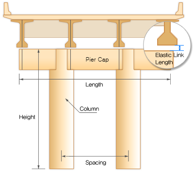
弾性連結長さ:主桁下フランジと橋脚柱頭部との間の支承ギャップを弾性連結長で表現
橋脚
材料 : 橋脚に使用する材料特性を入力しますクリックして、新しい材料を追加、または既存の材料を変更可能です
柱頭部 : 柱頭部の有無を選択します
断面 : 柱頭部に使用する断面を選択します クリックして、新しい断面を追加、または既存の断面を変更可能です
長さ : 柱頭部の長さ
柱部
断面 : 柱部に使用する断面を選択 クリックして、新しい断面を追加、または既存の断面を変更可能です
高さ : 橋脚の高さを入力します。詳細設定:異なる橋脚ごとに高さを個別設定可能です
間隔:2本以上の柱を定義する場合、橋脚柱間の距離を指定します。3本以上の場合、異なる間隔をカンマ区切りまたは「@」記号で入力(例:「10, 12」または「2@10」)
橋脚支持
固定 : 橋脚の下端を固定端で定義
バネ支持 : 橋脚の下端をバネ支持で定義
バネ剛性 : バネ支承を選択した場合、水平方向および鉛直方向のばね剛性を入力します。詳細:異なる支持条件ごとに剛性を個別設定可能