
機能
- 主桁およびダイアフラムの特性、タイプ、位置、アライメントを定義します。
- 主桁とダイアフラムの入力オプションは、主桁の種類(プレキャスト桁タイプかスプライス桁タイプ)によって異なります。主桁の種類(プレキャストまたはスプライス)は、レイアウトタブで定義されます。
経路
- メインメニュー:[ウィザード]タブ > [PC橋]グループ > [PC合成桁橋]
入力
図. PC合成桁橋ウィザード断面ダイアログボックス
デッキ厚さ
上部デッキの厚みを入力します。
「全て梁要素」タイプ(レイアウト – 主桁タイプ を参照)の場合、この値は横方向ダミー断面の板厚として使用されます。
「デッキ:板要素」の場合、この値はデッキの板要素の厚さとして適用されます。
ハンチ高さ (デッキ:板要素、桁:梁要素)
デッキと主桁の間の距離を指定します。この間隙は剛体連結で接続され、縦方向の間隔は板要素のサイズによって決まります。
ハンチがゼロの場合 → デッキと主桁の間に隙間は生じません。ハンチがゼロでない場合 → 指定された値に応じて隙間が生成され、剛体連結によって接続されます。
桁の本数
生成する主桁の個数を入力します
桁オフセット : 基準線と各主桁の中心線との距離を指します。
オフセットが基準線の左側(橋軸方向)にある場合は負の値、右側にある場合は正の値として入力します。
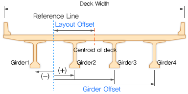
図. 桁オフセットのルール
材料
デッキ : デッキ要素に使用する材料特性を選択します。全て梁要素を使用する場合、デッキの自重が含まれます。また、選択したデッキ材料に基づき、比重がゼロの同じ特性の追加材料が自動的に作成されます。グリルエージ法などの全て梁要素 のモデリングでは、デッキの横方向剛性を確保するために横梁(ダミービーム) が必要です。
桁 : 主桁要素に使用する材料特性を選択します。
横梁:横梁(ダイアフラム)に使用する材料特性を選択します。
クリックして、新しい材料を定義するか、既存の材料を修正します。
横方向デッキ要素 (全て梁要素のみ)
ダミーデッキ用の矩形断面は、デッキ厚および横方向デッキ要素の間隔に基づいて自動生成されます。
間隔 : 横方向デッキ要素の間隔は、以下のいずれかの方法で定義できます。
分割数 : 横方向デッキ要素の間隔を、全桁長さを基準とした分割個数で入力
距離 : 横方向デッキ要素の間隔を直接入力
支間の分割数 : 各支間ごとに分割数を設定する方法(例:「3@5」や「5,6,5」など、3径間の橋の場合)。
角度タイプ : 横方向デッキ要素のスキュー(斜角)は、以下のいずれかの方法で定義できます。
斜角 : 「レイアウト」タブで定義された支点の斜角に沿って横方向デッキ要素を配置。
主桁に直角 : 主桁の橋軸方向に対して直交するように配置。
メッシュサイズ (デッキ:板要素のみ)
デッキの板要素のサイズを指定します。
プレート要素のサイズ
デッキ、ウェブ、およびフランジの板要素のサイズを指定します。
隔壁情報
ダイヤフラムは主桁の安定性を高め、荷重分配に寄与します。スプライス主桁タイプでは、通常、スプライス部にダイヤフラムが設置されます。
隔壁断面の定義
各ダイアフラムの断面を定義します。ダイアフラムの斜角は、レイアウトタブで設定された斜角に従います。
中間間隔
次のオプションのいずれかを選択して、中間ダイアフラムの位置を定義します。
距離/支間の分割数(プレキャスト主桁タイプのみ)
中間ダイアフラムの位置は、間隔距離または支間ごとの分割数を指定することで設定できます。この距離および分割数の情報は、各径間の主桁長に適用されます。
距離 / スプライス当たりの分割数(スプライス主桁タイプのみ)
スプライスごとの中間ダイアフラムの位置は、間隔距離または スプライスごとの分割数 を指定することで設定できます。
図. ダイアフラムの位置
Adv...: Advanced Diaphragm.
プレストレスト合成桁橋のモデリングにおいて、個々のダイアフラムの有無を選択できます。
End Support
橋台に設置される桁端部のダイヤフラム
Pier Support
橋脚位置に設置される橋脚部のダイヤフラム
スプライス支点(スプライス桁タイプのみ)
スプライス位置で桁同士を接続するスプライスダイアフラム
Intermediate
支点間の中間位置に配置される中間ダイヤフラムです。中間ダイヤフラムの数は、指定した間隔に基づいて決定されます。つまり、間隔を入力することで、中間ダイヤフラムめの数を設定・調整できます。
名称
各ダイアフラムの断面形状を選択
桁情報
主桁の断面は異なる形状に設定でき、最適化することでより経済的な設計が可能です。
本セクションでは、標準的な内部プレストレスト合成桁 の情報を入力し、縦方向に異なる断面を設定できます。ウィザードでは 1本の主桁 の情報を定義しますが、ウィザード実行時に指定した桁数および桁のオフセット距離に基づいて、他の桁が自動生成されます。また、外桁と内桁でスラブ幅が異なる場合、プログラムが外桁の張り出しスラブ幅を考慮した合成桁断面を自動的に作成します。
桁断面の定義 : 主桁に使用する断面を定義します。指定できる断面は以下のいずれかです。
- 合成I型桁(Composite-I)
- 合成T型桁(Composite-T)
- 合成プレストレストコンクリート桁(Composite-PSC)
- 一般合成桁(Composite General)
分割数 : 主桁ラインに沿った分割数を設定します。各分割ごとに断面形状と開始・終了位置を指定します。
対称設定 (スプライス主桁タイプのみ) : スパンの構成が対称である場合、選択。例えば、ガーターラインに沿って分割番号が5でSymmetryオプションが選択された場合、ガーター情報テーブルにはDivision No.1、No.2およびNo.3行のみ表示されます。その後、プログラムは橋梁の半分に対する情報を基盤に対称的な形状を生成します。
「対称」オプションを有効にすると、桁の分割情報が対称に適用されます。これにより、主桁情報テーブル内の行数が削減され、橋梁形状が対称に生成されます。
例)主桁ラインの分割数が5の場合、対称オプションを有効にすると、第1~3分割のみを入力すれば、自動的に対称形状が作成されます。
名称: 使用する主桁断面を選択します
開始/終了 :各主桁断面の開始位置と終了位置を入力
プレキャスト桁 / スプライス桁の入力方法の違い:
プレキャスト桁タイプ:各径間ごとに主桁情報を入力
スプライス桁タイプ:主桁は スプライス位置で分割され、各セグメントごとに断面を設定
SP(スプライス位置) :断面の終了位置がスプライス位置の場合、「SP」にチェックを入れる
スプライス位置ごとに主桁が分割されるため、均一な断面形状であってもスプライス位置で必ずセグメント化される
各セグメントに対して、詳細な架設順序やプリテンションPC鋼材の設定が可能
SP (スプライス主桁タイプのみ) : セクションの終了位置がスプライス位置である場合にチェックを入れます。スプライス位置で主桁が分割され、それぞれの桁セグメントとして扱われます。分割された桁セグメントごとに、詳細な架設手順やプリテンションPC鋼材の設定が可能です。スプライス桁タイプでは、桁の断面が全区間で均一であっても、スプライス位置で必ず分割されます。
10点目の要素の生成 : 自動的に各径間を10等分する構造グループが作成されます。径間の大きい橋梁の場合、10分割点を検討位置とするために提供される機能です。